A cognitive redesign of a Glider Dashboard
A collaborative project conducted by Isabelle Kjellström, Adam Dahlberg och Dennis Delwér.
This project was conducted with the aim to redesign an existing human-machine system from a cognitive ergonomic perspective. The project was in collaboration with a local glider club where a number of glider pilots, with various experience levels, and flight instructors participated. By using different methods, a modern glider cockpit was evaluated, and then the dashboard was redesigned with the aim to decrease the cognitive workload of the pilot. Due to Covid-19, the project was conducted entirely online, meaning that interviews were held via Zoom, and analysis of current glider systems were performed by using pictures, video clips and a glider simulator.
For a Concept background, Concept overview and a list of the Methods, tools & PC programs used, please scroll down.

Concept background
Gliders utilize warm rising winds to be able to fly for long periods of time without the use of an engine. A flight starts on the ground with a take-off checklist where the glider is prepared for take-off. Then, the glider gets towed up in the air with the help of a tug-plane and the glider pilot releases the tug line when the glider is possible to soar on its own. The glider then flies on its own, and the pilot is constantly is looking for thermal winds to gain height and fly longer distances.
Taking a look inside a cockpit of a modern glider, this is how it could look like (see Figure 1). First of all, there is the navigation system, highlighted in red, consisting of a navigation computer displaying things like the position of the glider, a planned route, headings and GPS speed. There is also a Variometer displaying the speed at which the glider lifts or sinks, a speedometer showing the airspeed, an altimeter showing the altitude above the ground, and a compass showing the heading.
Next there is the communication system, highlighted in yellow, with a radio and a microphone. Lastly, there is the control system, highlighted in blue, mainly consisting of the joystick and rudder pedals used to control the glider.
The physical automation level is very low in gliders since there is no autopilot. the pilot, therefore, has to actively navigate the glider at all times. Moreover, cognitive automation has been increased throughout the years, as gliders today can display more and more information directly to the pilot in the cockpit.
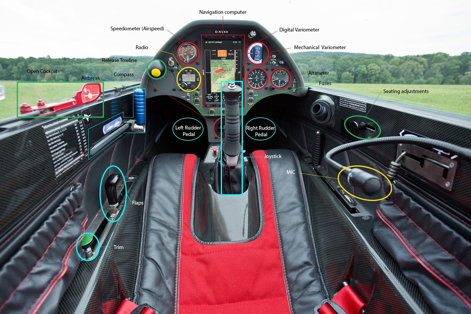
Figure 1. An example of what a modern glider cockpit might look like today.
The concept
The group chose to focus on the placement of instruments in the cockpit as well as the readability of some instruments with the aim to minimize the visual stimuli in order to free up mental resources from the pilot and make the use less cognitively demanding and in turn avoid pilots making small skill-based mistakes.
Taking a closer look, the project group first have kept all the instruments from before but have combined digital instruments with mechanical instruments (see Figure 2). This makes it possible for all instruments to display instantaneous values digitally which makes it easier for the pilot to quickly read and interpret the precise value on all the instruments. The values are also color-coded which means that for example on the speedometer the color of the value is green within its normal operating speed while it turns yellow or red within the speeds to be cautious. This makes it possible for the pilot to, with just a glance, see the general status of the plane. By having the digital and mechanical values within the same instrument, it makes it possible to minimize the total amount of instruments in the cockpit while still keeping the safety aspect where if the battery dies or the electrical system struggles, the mechanical part of the instrument still works. Furthermore, the color of the pointers on the mechanical instruments has been changed to increase the contrast and make it easier and quicker for the pilot to read the value of an instrument.

Figure 2. Regular flight mode.
Moving on, we have changed the shape of the radio to be rectangular instead of circular to make it easier for the pilot to distinguish between the navigation system and the radio system.
One of the biggest changes is the addition of a HUD, or heads up display. The heads up display allows the pilot to see the values of the most important instruments without losing focus on the environment outside of the cockpit. It also makes it easier for the pilot to get an overview of the status of the plane since the instruments are centered in the view of the pilot, and it also relieves the pilot as it only shows the most relevant information. Moreover, the HUD has 2 different modes. The first mode is for regular flight which can be seen on the screen now and it shows the speedometer, variometer, altimeter and compass on the HUD.
The second mode is for IMC-flight, or instrument flight, and in addition to the instruments just mentioned it adds a gyro and a timer to the HUD (see Figure 3). This makes it possible for the pilot to navigate the plane inside of clouds only by looking at the HUD.

Figure 3. Instrument flight mode.
If the conditions make it hard to read the HUD or if the pilot for some reason does not want to use the HUD, it can easily be folded down behind the dashboard to avoid it from obstructing the view out of the cockpit (see Figure 4).

Figure 4. The HUD folded down.
In figure 5, you can see our concept to the left and the reference plane to the right. The arrows show how the vision of the pilot is supposed to move between the different instruments especially during IMC-flight but also during regular flight. As you can see the pilot does not have to move the vision as much in our concept since the most important instruments have been placed in the center of the dashboard.

Figure 5. Redesigned concept to the left and the reference plane to the right.
The same goes for the HUD where we can see that the pilot has to move their vision even less.
With all these changes we hope to make it easier and quicker for the pilot to read the instruments, we hope it will be easier for the pilot to find the relevant data, and as a result free up mental resources from the pilot and make the use less cognitively demanding.
Methods, tools & PC programs
The project work was highly collaborative, meaning that all project group members were present throughout the entire design process. The following methods, tools, and PC programs were used during the project:
Literature studies
System analysis
Human-machine system modeling
Cybernetic system modeling
Task & operator analysis
Automation analysis (physical & cognitive)
Hierarchical Task Analysis (HTA)
Use cases
User relations analysis
Perception, attention & awareness analysis
Mental resources & mental workload
NASA-TLX
Generic task specification (GTS)
Wickens’ resource model
Distributed cognition & mental models
Applied Cognitive Task Analysis (ACTA)
Distribution of Cognitive Processes
The Abstraction Hierarchy Model
Mental models
Emotions & performance
Hesselgrens Emotional Scale
Emotional reactions
Interaction errors & risk
Risk & safety analysis
Rasmussens’ SRK-model
Cognitive Walkthrough (ECW)
Predictive Use Error Analysis (PUEA)
Decision making
ECOM-model
The ETTO principle
Expertise
Operator expertise analysis
Concept development
Listing of requirements and guidelines
Digital prototyping using Miro (PC program)
User evaluation through user interviews